Automates and Organises Quality Assurance in Radiation Therapy and Medical Imaging

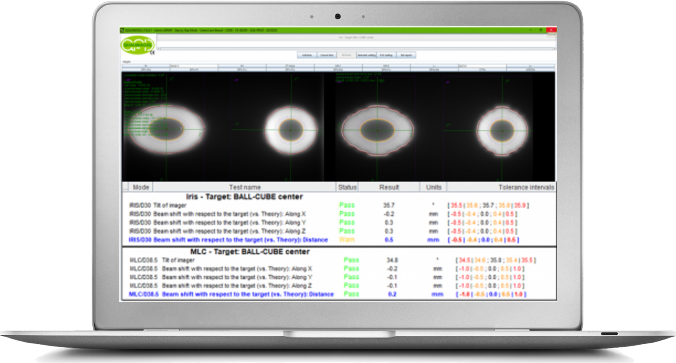
AUTOMATIC ANALYSIS OF THE "AUTOMATIC QUALITY ASSURANCE (AQA)" TEST BUT CARRIED OUT WITHOUT FILM BY USING THE CK-IMAGER HIGH-ENERGY PORTABLE IMAGER
The “AQA” test is the Cyberknife adaptation of the Winston-Lutz test. To perform this test, ACCURAY provides their BALL-CUBE phantom which contains fiducial markers allowing to align it with the kV imaging center and a removable metal ball in its center to locate this kV imaging center in the 2 Gafchromics films arranged orthogonally in the center of the phantom.
We offer a test equivalent to the AQA test in which the 2 films have been replaced by our high-energy portable imager CK-IMAGER :
-
“Target > BALL-CUBE” test: A “Fiducials” type tracking targeting the fiducial markers contained in the ACCURAY BALL-CUBE cube positioned on our CK-SLAB-CUBE plate itself positioned on the tilted imager of 36 ° from the horizontal and fitted with its CK-COVER-TRUE cover, all inclined relative to the horizontal using the CK-COVER-TILT accessory, 2 beams programmed in "QA" anatomy with an "AQA" type source-nodes path and a planning aimed at the volume target which delimits the metallic ball contained in the center of the CUBE-BALL phantom.
The tilt of the imager allows the 2 beams to be viewed on a single image automatically analysed by the module regardless of the collimation chosen (cone, iris or MLC).
In addition, this module also makes it possible to automate the following test carried out with our high-energy portable imager CK-IMAGER:
-
“Target > Fiducial markers" test: A “Fiducials” type tracking targeting the 5 fiducial markers contained in our CK SLAB-FIDU plate positioned on the imager equipped with its CK-COVER-TRUE cover installed horizontally, 5 beams programmed in "QA" anatomy with a "single beam" type source-nodes path and a planning aimed at the 5 targets distributed around a central target.
Important Note: This test is not equivalent to that recommened by ACCURAY because, on the one hand, it only uses a single source node, and on the other hand, it is not feasible with the MLC
The aim of the 2 tests is to compare the positions of the centers of the irradiation fields measured on the images with their expected position, either coming from a reference image acquired at the end of the "D-MAN" calibration, or coming from of theoretical positions obtained by trigonometric calculations.


The first test is recommended for cone and iris type collimations because this test is simpler to carry out, while the second test is mainly used with the MLC because the "Isocentric" planning type is not available for. this type of collimation.
The Imaging Center test : This module automates the analysis of the 2 images of the “isocrystal” test object provided by ACCURAY to materialise the installation of the imaging center. These 2 images obtained with the 2 on-board imagers of the CYBERKNIFE must be converted into DICOM format with the CK-CONVERT component (See below).
Lastly, the module automates the analysis of the high-energy image aquired with the CK-IMAGER as part of the pre-test. This makes it possible to specify the geometry of the irradiation, a geometry essential to know with precision in order to carry out the trigonometric calculations making it possible to obtain the theoretical positions of the irradiation fields. on the image.

The 2 CK-COVER covers and the 2 associated CK-SLAB plates are essential for this module.
Associated high-energy portal imager: CK-IMAGER from QUALIFORMED and its indispensable accessories CK-COVER-TRUE, CK-COVER-DUMMY, CK-COVER-TILT, CK-SLAB-FIDU and CK-SLAB-CUBE.
Resources
You need a user manual? please contact us.
Your brochure request has been added to your Download Cart.
At the end of your visit:
- Please click the "YOUR DOWNLOADS" button at the top right,
- Complete the form and SEND it.
You will get the documents shortly by email.


